Tuesday, 18 November 2014

FYP2 WEEK 1 (1)

Title :Research about the relay DPDT (Double Pole Double Throw)
ANALYSIS
- For this project, relay DPDT will be used as a backup if there is any power failure.

- Power failure means there is no power supply. There is an alternative way that I can use by using battery of 12 volt. Therefore, this project will be added one more relay of DPDT as a function to replace power supply.

Terminal Pins
A Double Pole Double Throw Relay comes with 8 terminal points.
The terminals are COIL, COIL, COM, COM, NO, NO, NC, NC.


Terminal Descriptions

COIL- This the is the COIL terminal. These are the terminals where you apply voltage to in order to give power to the coils (which then will close the switch). Polarity does not matter. One side gets positive voltage and the other side gets negative voltage. It doesn't matter which order. Polarity only matters if a diode is used.
NO- This is Normally Open switch. This is the terminal where you connect the device that you want the relay to power, when the relay is powered, meaning when the COIL receives sufficient voltage. The device connected to NO will be off when the relay has no power and will turn on when the relay receives power.
NC- This is the Normally Closed Switch. This is the terminal where you connect the device that you want powered when the relay receives no power. The device connected to NC will be on when the relay has no power and will turn off when the relay receives power.
COM- This is the common of the relay. If the relay is powered and the switch is closed, COM and NO have continuity. If the relay isn't powered and the switch is open, COM and NC have continuity. This is the terminal of the relay where you connect the first part of your circuit to.

Wednesday, 21 May 2014

WEEK 14

Title :  DISCUSSION WITH TECHNICIAN ABOUT RELAY CIRCUIT 


For this week i has meet with technician and ask him about the relay connection, he give some advice about the connection and after discussion with him, i design the circuit of relay that suitable to use in my project.


Figure above show that my relay circuit after make some editing and correction about symbol and also proper design 


WEEK 13

Title : Schematic Diagrams


For this week i design the schematic diagram for my pic circuit, from the figure show that all basic component that pic circuit require which is oscillator circuit, the grounding circuit and also the power supply circuit that require to complete the basic of PIC circuit.

WEEK 12

Title : Draw Schematic Diagrams


 Figure 1: Bluetooth Module Diagram
Figure 2: Voltage Regulator Diagram


            For this week i'm have make some research about my schematic diagrams for my project, as u can see at figure 1, this will my Bluetooth Module connection and also the value of resistor that will connect to this circuit and also the voltage value take Bluetooth Module require which is 3.3V

           To get the require voltage value which is 3.3V the circuit need the voltage regulator to produce that require voltage value and the figure 2 show how the circuit from voltage regulator (LM 317) connection to produce the require voltage value   


Sunday, 11 May 2014

WEEK 11

Title :  DISCUSSIN WITH STUDENTS FYP2


This is how my friend project look like, he use bluetooth module to control the parking system and this already done and test the circuit and it was 100% working nicely.


This is how bluetooth module look like, this is bluetooth module connection circuit, my friend explain to me about this connection and he told me that bluetooth have primary and also slave that fuction as transmit and receive the data and all of that was already install in the bluetooth module. 


WEEK 11


Title :  DISCUSSION WITH STUDENTS FYP2 


For this week I went to my friend's house to asking about the hardware system working for bluetooth module because now he taking FYP2 and he also using Bluetooth module for his project 


The picture show that my friend was explain to me the bluetooth circuit diagram about how working principle and also about connection 

Right now he explain to me about his project FYP2 that also use Bluetooth module to control parking system, with his explanation it help me to construct  my project and also help me to get ideal how to design my project.

WEEK 10

Title :  PRESENTATION FYP1 


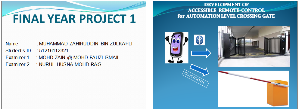
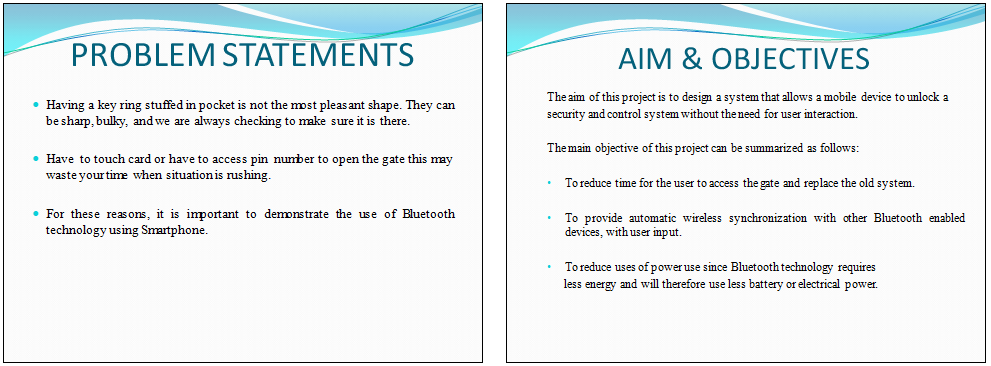
This week i has presentation FYP1, there have 2 assessor  to assess my presentation and the figure below is my slide show about presentation for my project.